Homebuilt Wood Lathe
In 1997, I looked at many different designs for homebuilt lathes while trying to decide if I wanted to buy or build a wood lathe. I decided to build one and it turned out to be stable, quiet and works quite nicely. I liked different elements of some of the lathe designs that I saw in books and magazines so I decided to pick and choose the elements that I liked to create my own lathe. The lathe that you see here is based on two different homebuilt lathes described in the following references:
Carlyle Lynch, "Low-Cost Wooden Longbed", in Lathes and Turning Techniques, The Best of Fine Woodworking, Taunton Press, Inc, 1991, pp 72-74.
WOOD (Better Homes and Gardens), ed. Blume, J.D. , "Woodworking Tools You Can Make",Meredith Books, 1991, pp 54-63.
Technical Specs.
16 Speeds via step pulleys and wood leadscrew motor mount. 4313 to 690 RPM.
Swing: 16 inches over bed.
Headstock Spindle: 1"x 8 TPI RH #2 Morse Taper Inboard 1"x 8 TPI LH Outboard
Tailstock: 1"x 8 TPI RH #2 Morse Taper
Max. Distance Between Centers. 48" Max.
Outboard Swing: 6' plus (Never would try it, but theoretically possible)
Motor: 1/2 HP , 1725 RPM, GE
Electric Motor Flange Block Ball Bearings (Sealmaster bearings) support headstock spindle.
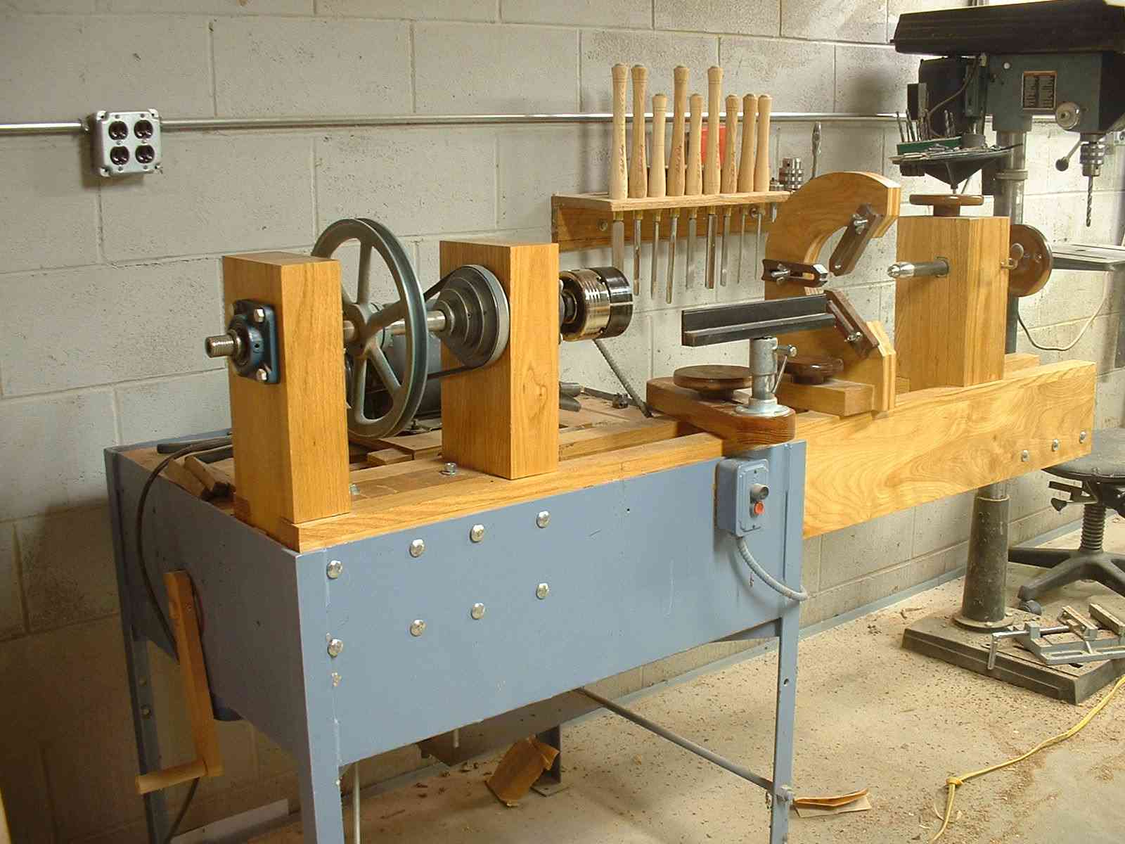
I liked most aspects of the WOOD Mag. lathe except the inability to turn outboard, so I decide to pattern the headstock after Lynch's design. I liked the way the WOOD Mag. design allowed one to use hand-wheels above the ways to tighten and loosen the tailstock and toolrest. It seemed like an inconvenience to have to reach under the ways to do this. I built the ways out of 3/4" birch plywood and 13/16" red oak. The plywood was laminated 3 thick and topped with red oak. I laminated the head and tail stocks out of red oak. The tail stock is just like the WOOD Mag. version just variations in materials. I made the tool rest base out of black locust, very hard, very strong. One interesting addition to this lathe is the motor mount. The motor mount moves in a separate set of parallel ways. The mount moves under the influence of a 1" wood threaded dowel. By turning a crank on the stand, one can precisely position the motor such that the step pulleys are aligned in a desired position. The motor mount itself is hinged to make belt changes easier and to allow for the different circumferences that change the distance between the motor shaft and the headstock spindle when the motor is in a nonstandard position. Whether or not I actually need 16 speeds is another matter. I could probably get by with just 4 which would not require a moving mount, but this would not be as interesting ;-). One of the main objectives in building this lathe was to keep costs low. I have a nice stack of red oak, black walnut and locust lumber which came off of Dad's farm so I did not have to buy any hardwoods. I scrounged around for parts and managed to get several key items for little or no money (e.g. motor, bearings, etc). I purchased a used face plate, 4 step pulley and a 6" toolrest from Dave Trey, (Trey Toolworks, Troy OH ) for $20 + shipping. Flange blocks and another 4 step pulley from CT Farm and Country. I had some local Vo-Tech students machine the headstock and tailstock spindles. These students did a fine job. This lathe was built in 1997 before I started building metal working equipment.
I made my first tools, a bowl gouge and a spindle gouge from a piece of 3/8" drill rod which I annealed, shaped, hardened and tempered to about 58 Rockwell (dark straw). These worked fine for the black walnut hand-wheels and handles which I turned for the lathe itself. That about covers the major components other than centers which I had to buy new. I added up the cost of the elements I had to pay for and it came to $267. If I did not scrounge and go the salvage route I estimate that the cost would be around $600. If you were to buy a new commercial lathe with this capacity it would cost $1500 +. I built this lathe mostly with hand tools. Dadoes and grooves were cut with a Stanley #45 combination plane (Precursor to the modern router :)). A drill press is quite useful for boring the holes for the spindles. It is nearly impossible to bore a large straight hole without one. Planes were also indispensable. Up until this time, my shop was well equipped to handle straight, square work making anything round was a major problem. If you have the tools, are not in a hurry and don't mind scrounging, I recommend building. You can make a nice lathe with a large capacity with little money. The other low cost option is to buy a used lathe, if you can find one. I considered this and I am sure that I would have bought one if I could have found one within a 300 mile radius. I looked for about 2 weeks and could not find what I wanted and in the mean-time, I scrounged up some components and decided to build. This was the first lathe that I built . The only other wood lathe that I have used is a circa 1950's Craftsman model which was not in the best of shape. The homebuilt is easier to use and has larger capacity. Not having any experience on other lathes, I cannot make a fair comparison of how well the homebuilt stacks up to other lathes (e.g. Delta/Rockwell, Record, Conover, General etc. which all look quite nice if you've got the cash).
Recent additions to the lathe include a Super Nova Chuck, a set of HSS Robert Sorby turning tools, new Woodcraft toolrests and a steady rest. The lathe has handled large hollow vessels, long spindles, a 9 1/2' oar ( with tailstock mounted on another table, not recommended), 13 inch dia 3/8 thick ring patterns (see Grinders), and many other items. It has been in light use for about 10 years and continues to serve me well.
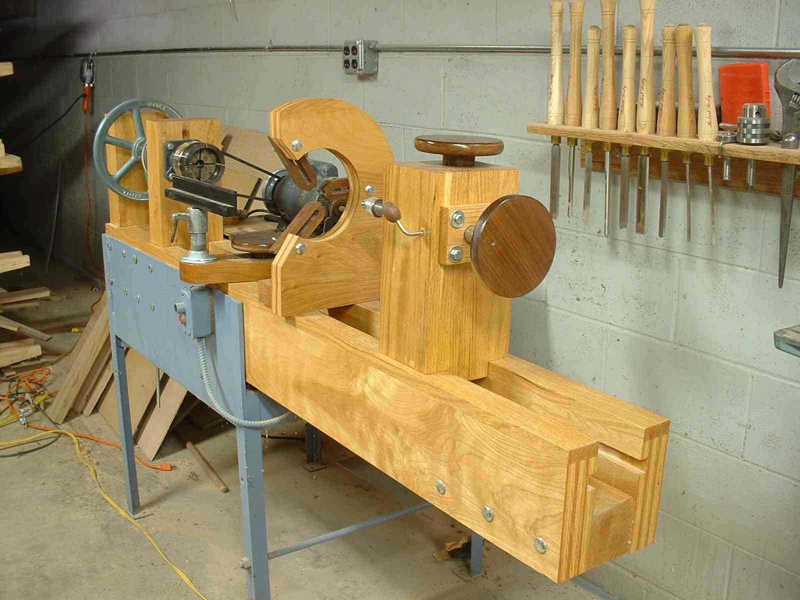
I have had numerous requests for more detailed photographs of the lathe from individuals interested in building their own. Below, you will find some close-up photos that may be useful to those who are building a homebuilt lathe.
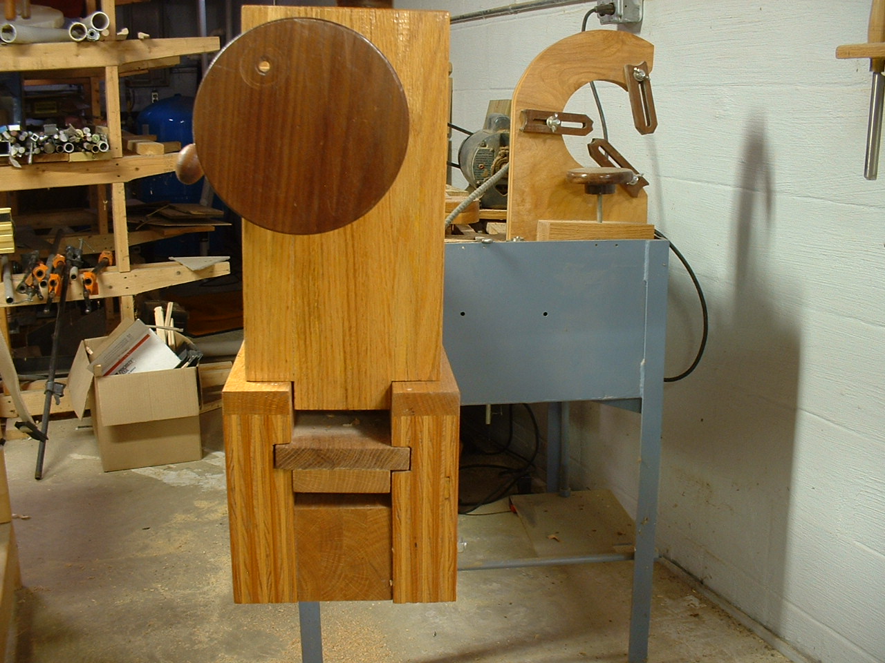
A view of the tailstock near the end of the ways. Note that the ways are constructed of 3 layers of 3/4" birch plywood topped by solid red oak. To clamp the tailstock in place, the T-block is pulled towards the top of the groove using a piece of 3/8 threaded rod which is secured in the top walnut clamping wheel with epoxy. A 3/8 T-nut is embedded into the bottom of the T-block. The tailstock is constructed of several pieces of solid red oak that have been glued-up. The hole for the threaded rod is cut prior to lamination.
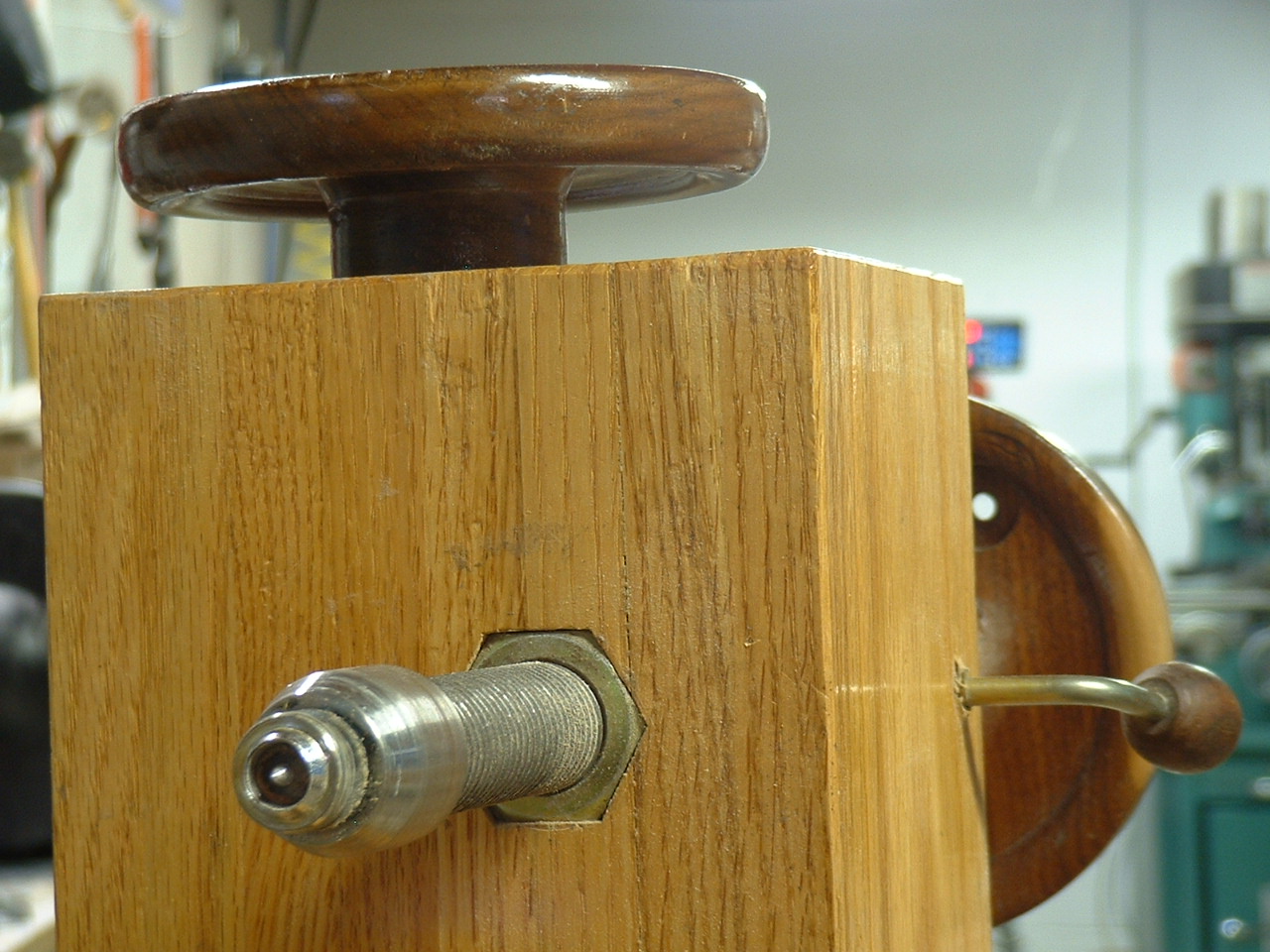
The knob on the side of the tailstock passes through a threaded insert and presses against a piece of brass rod which in turn locks the tailstock spindle. The hole for the tailstock spindle is cut slightly oversize after the lamination. The block with 4 lag bolts on the end of the tailstock is used to align the tailstock spindle after assembly since it is quite difficult to obtain perfect alignment of the headstock and tailstock spindle during construction. On a metal lathe, such alignment can be achieved by using a boring bar mounted in the headstock spindle to bore the tailstock. In the case of a wood lathe, the adjustable block works fine. Note that the hole through the adjustment block is bored to a close sliding fit to accommodate the tailstock spindle.
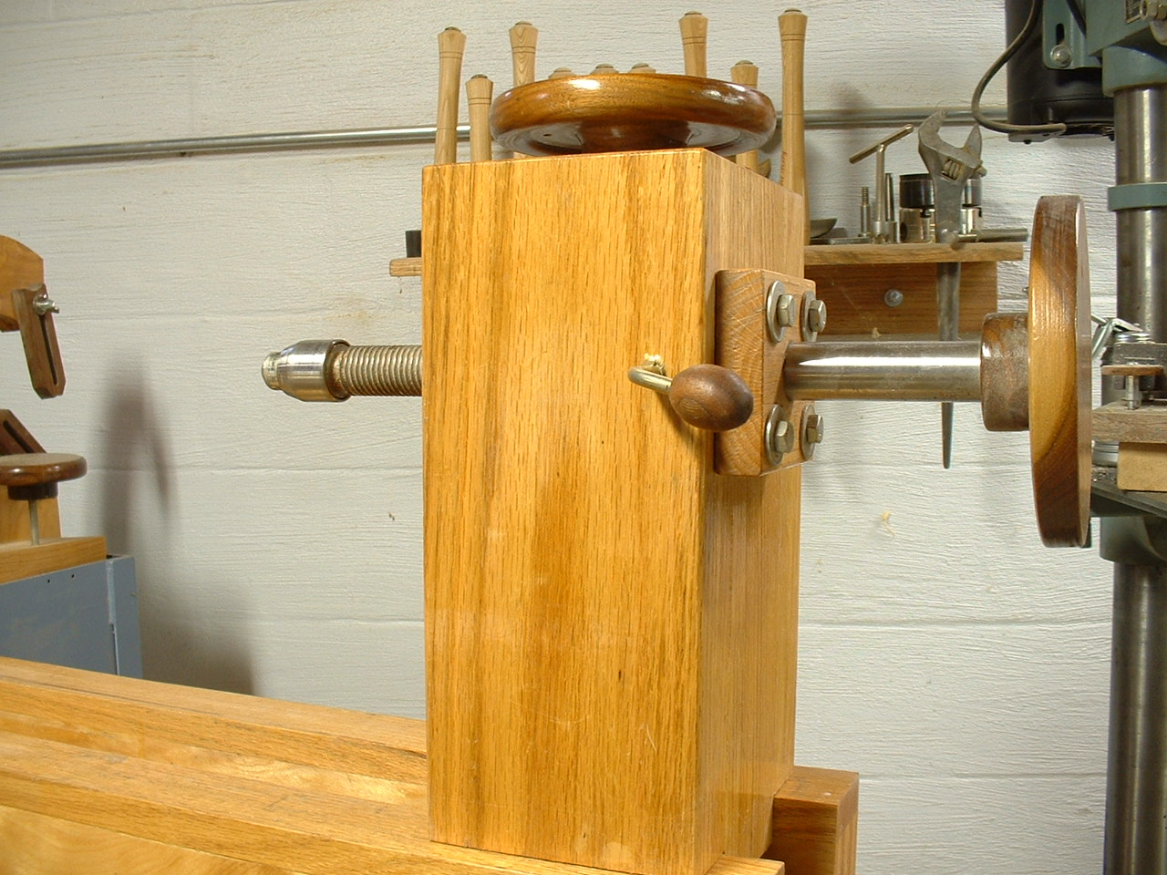
A view from the front of the tailstock reveals that the spindle is advanced or retracted by turning the threaded end of the spindle through a nut that has been embedded in a hexagonal mortise. The mortise is cut for a press or driving fit of the nut into the tailstock block. There are certainly more elegant approaches to making an adjustable tailstock. A close inspection of a metal lathe will reveal more desirable methods; however, the approach taken here has proven to be simple and works well on a wood lathe.
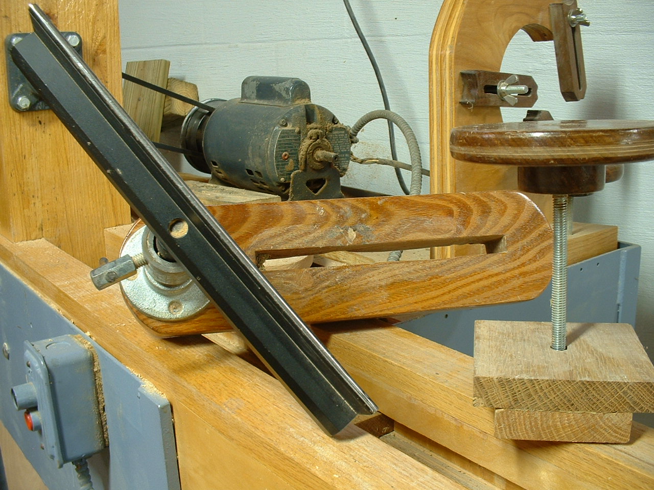
The toolrest is mounted on a laminated black locust block with a through mortise slot cut to accomodate a 3/8" threaded rod that is inserted into T-block that fits the groove in the ways. The steel components are made from black-pipe fittings. The threaded rod is secured to the walnut wheel using epoxy. The toolrest is 12" long and was obtained as an aftermarket item from Woodcraft Supply.
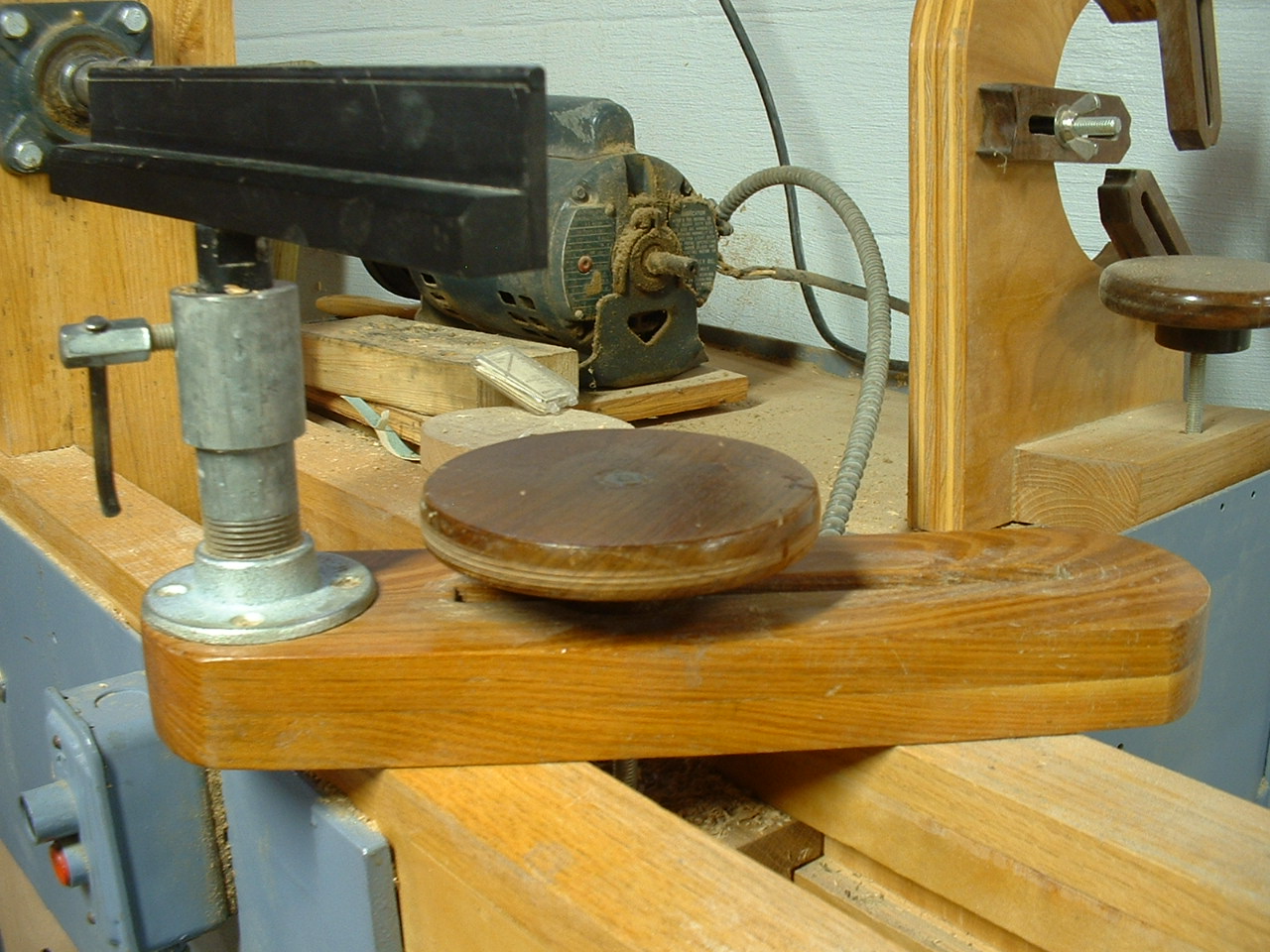
The toolrest assembly removed from the lathe and turned on side for clarity.
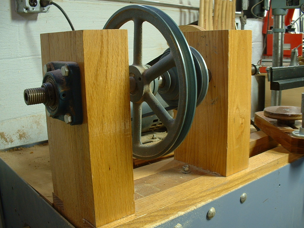
Detail view of the headstock. The spindle is mounted on self-aligning flange ball bearings. The flanges are secured with 4 lag bolts. The two bearing supports that comprise the headstock are made from laminated red oak.
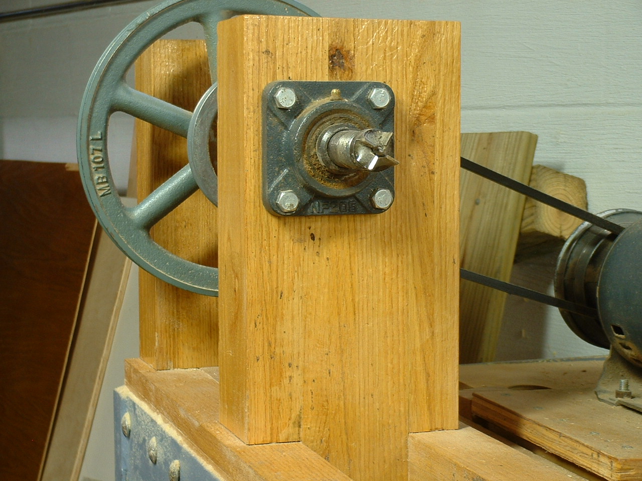
The lathe spindle is threaded on both ends to support spindle and bowl turning. The inboard end is threaded 1"-8 TPI RH while the outboard end is threaded 1"-8TPI LH. Frankly, I have never used the outboard end for turning. The inboard side has plenty of capacity for my application. With this in mind you might consider making your tailstock all one piece as described in the "Wood Magazine" book. Be sure to have a hole bored all the way through your spindle so you can free Morse taper accessories.
Copyright © 2003-2007, David B. Doman PhD, All rights reserved.